


 Copy to clipboard
The medical device manufacturing industry has certainly been under a significant amount of pressure lately with increased regulations and the demands for more efficient, cost effective and higher quality production of their products. Additionally, more sophisticated devices are in development to utilize advanced materials, structures and design. As those innovations progress through the product lifecycle into the manufacturing phase, the industry continues to struggle with ways to adequately test product quality that meet FDA requirements but don’t break the bank. The NASA philosophy of “better, faster and cheaper” certainly would be a nice approach. However, within an FDA-regulated industry, and a highly competitive one, “better” is certainly an area where compromise is not allowed.
High-end image analysis software, integrated into the manufacturing process, is a relatively new and particularly strong way to improve the speed, quality and cost of producing medical devices. Imaging can be particularly valuable in two areas. The first area is in assessing structural integrity of manufactured parts. The second is the assessment and quantification of tolerance within the manufacturing process.
The introduction of advanced materials and sophisticated medical device designs demands that manufacturing achieve new levels of quality assurance with consistent runs in the manufacturing line—avoiding cracks and ensuring that fine structures are intact. The use of advanced imaging and analytical software in ensuring structural continuity can provide a consistent and cost-effective real-time way to identify issues, quantify the number of issues, and in some cases, provide causative information.
Take, for example, production of a cardiac stent, in which the manufacturer needs to determine if the fine mesh is connected and if not, discern what errors may have taken place in the manufacturing process. One way is to manually visually inspect it—the current state of art. Conversely, conducting high-resolution CT scans of these devices as they emerge from the assembly line brings a new dimension to the ability to detect the integrity of the device. Using the CT technology, it is possible to create a three dimensional view of the inside of each part, including the structure and consistency of the materials. Once you have this full scan of the part, it is possible to introduce automated software that can easily detect if there are any breaks in the structure or if material looks out of specification somewhere in the part. The output of the software can then be used to provide a “score” or a priority rating for the newly created part. This score can be used to quantify the overall acceptability of the part based on a number of key parameters that are critical to the quality. Structure can be assessed, material thicknesses can be measured, material consistency can be quantified, or many other key metrics can be automatically used in grading of the part. The output of this analysis can be used to prioritize a human-based inspection and QA process, so that the parts that seem to be most troublesome can be inspected first and thoroughly, while the parts that are more in line with expectations can be given a more rudimentary assessment. This analysis can be performed on every part that rolls off the manufacturing line, all while providing clear and concise documentation and audit history.
Of course, looking inside a part for such non-destructive testing is a very sophisticated technique. and therefore may not be required for every type of device that is being manufactured. However, if you don’t need to assess the inside of the device, it is almost assured that you will have a need to measure manufacturing tolerance of the dimensions of the device. Keeping products within manufacturing “tolerance” can be a real challenge for medical device manufacturers, because often the specifications are quite strict. This is not assessing the internal structure of the device, necessarily, or looking to see if it’s cracked or consistent, but rather a technique that will help the manufacturer determine if what was built lies within the manufacturing tolerance required by the designers.
Current, common tolerance testing involves a statistical technique. For example, typically for every 100 devices that are produced, a subset is sampled and measured to determine if the lot is within specifications. The measure is usually performed manually, with the person performing the measurement doing the work, then completing a form to document the measurements and the process. This manual method, while meeting minimum requirements, presents a whole host of problems in the event of an FDA challenge, including human errors, inconsistencies and auditing costs.
A technique that is being adopted more readily is the use of surface scanning lasers to assess the exact measurements of the produced part. The surface scanning laser can measure the surface of a part to a high degree of accuracy and produce a wireframe digital representation of the part in three dimensions. Then, using sophisticated software that can align this mesh of the actual part to a CAD representation of the part, it is possible to assess the result of the manufacturing against the desired specifications. This technique, called co-registration, is an image analytics technique that takes two images—two representations—of the same object and determines how those two images relate to each other spatially so that you’re actually looking at the same element in the same coordinate system.
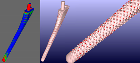
Sophisticated scanning is a better approach that is beginning to be used in the manufacturing process. Using this laser technology, manufacturers will be able to quickly and accurately assess the surface quality of a part, and then co-register the original manufacturing specification against the actual part and automatically identify out of tolerance issues. For example, as you can see in Exhibit 1, it is possible to color-code areas of the part that are above or below the ideal model of the part.
Exhibit 1: Height Mapping
Height mapping for tolerance of a manufactured part provides assessment of an ideal part model.
Of course, advanced CT scanning techniques and laser surface scanning provide outstanding insight into the manufacturing process. However, in many cases, a simpler approach for imaging can leverage the full power of software analysis. Simple visible light camera images, combined with power analysis software, can be a very effective approach. Take for example the images of a circuit board seen in Exhibit 2. The image on the left is a simple photograph taken with a handheld camera, without the need for a sophisticated or expensive camera rig. Through the creation of analysis software, it is possible to confirm that the wiring has been done appropriately. This provides a powerful and cost-effective means for definitively checking the wiring process.
Exhibit 2: Wiring Assessment through Software Analysis
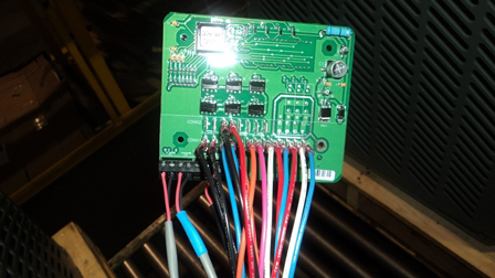

This circuit board image on the left was taken with a handheld camera without the need for a sophisticated or expensive camera rig. Through the creation of analysis software, it is possible to confirm that the wiring has been done appropriately.
Summary
Imaging techniques and analytical software are among the many new and groundbreaking techniques deployed by the medical device industry as key business strategies. Use of imaging allows innovative leaders to improve data accuracy for impending increased FDA scrutiny, reduce their QA costs to compensate for the impact of the medical device tax and improve manufacturing profitability. Imaging hardware and custom analytical and operational software can deliver strong manufacturing ROI, as well as a competitive price and quality advantage.
Tim Kulbago is Chief Executive Officer of ImageIQ, an imaging CRO and software development company located in Cleveland, Ohio.