Smart implants can provide objective information about the progression of healing after orthopaedic surgery. These data can help guide post-operative care, foster better outcomes and reduce lost work time. The technology exists to transform traditional orthopaedic implants into smart implants. So why aren’t smart implants being used in daily clinical practice?
A new generation of implantable sensors may be the missing link.
For decades, select researchers have instrumented hip, knee, long bone and spinal implants with implantable sensors. Measurements of pressure, temperature and force have helped to characterize the physical environment in and around implants during post-operative healing. Landmark research studies have demonstrated that force measurements can be used to monitor fracture healing in fracture plates. Force in interbody implants or pedicle screws can provide objective data on progression of spinal fusion. Force data from knee implants can be used to quantify ligament tension and balance in total knee arthroplasty.
While research studies have provided valuable data, the sensor technology has limitations which preclude its use in clinical practice. Strain gauges, the mainstay of orthopaedic implantable sensors, are permanently bonded to the surface (internal or external) of the implant. They must be connected to a signal conditioning circuit and telemetry system. The circuits require power and complex electrical connections. In state of the art systems, power is transmitted by inductive coupling from an external to an internal antenna. It is also necessary to provide a hermetic seal of the gauges, circuitry and telemetry. This means sensor systems are expensive, bulky and perhaps most importantly, they require significant modification of host implants for their incorporation.
Passive resonator sensors are fundamentally different from strain gauges. Passive resonator circuits have the advantage of simplicity. In its most simple form, a passive resonator circuit comprises two electrical components, a capacitor (C) and an inductor (L). When the two-component L-C circuit is excited with radiofrequency (RF) energy, it resonates. The resonant frequency is a function of both the inductance and capacitance. When either one changes, the resonant frequency is modulated.
The resonant frequency of an implantable passive resonator sensor can easily be measured wirelessly via an external antenna using a grid dip oscillator. The oscillator generates RF energy and sweeps a range of frequencies around the resonant frequency of the sensor. The RF energy causes the sensor to resonate. At its resonant frequency, the sensor absorbs energy which is observed as a “dip” on the oscillator. If the resonant frequency of the sensor changes, the dip will move accordingly. In this way, the resonant frequency of the sensor can be read dynamically.
Technology
Through a simple design, an L-C circuit can function as a passive, standalone force sensor. Physically, two coils of electrical conductors in close proximity to each other form an inductor. Similarly, two flat parallel conductive plates separated by a thin layer of dielectric form a capacitor. If the distance between the two plates of the capacitor changes, the capacitance is modulated and the resonant frequency changes accordingly. Applying a force to the capacitor will cause the dielectric between the plates to deform, which reduces the gap between the plates and in turn modulates capacitance and alters the resonant frequency. In this way, a simple L-C circuit can function as a force sensor.
Through a novel design, this can be achieved using a single component system with no electrical connections. In the single component design, one element acts as both inductor and capacitor. This is achieved using two flat parallel coils that are separated by only a thin layer of dielectric. When the flat coil inductors are in close proximity to each other, they also function as the capacitive plates.
What is unique is that there need not be any electrical connections between the two coils. Even with no electrical connections, the two coils comprise an L-C circuit. They have a characteristic resonant frequency that is detectable using a grid dip oscillator. The resonant frequency is a function of the inductance and capacitance. Capacitance can be modulated by loading the sensor and compressing the dielectric between the coils. In this way, the two coils comprise a complete force sensor with no electrical connections.
The flat coil inductors can be made using various gauge insulated wire of any conductor by winding the wire into coils until the desired diameter is achieved. (See Exhibit 1.) The wire is wound through epoxy, which bonds each loop of wire to the previous. This prevents the coil from unwinding once wrapped. The resting resonant frequency is a function of wire gauge, coil diameter and the gap between coils. The gap between the coils is equal to the thickness of the dielectric which separates them. The thickness of the dielectric can be customized to achieve the desired resting resonant frequency. In general, the thinner the dielectric, the lower the frequency. Dielectrics can be spin-coated, vapor deposited or manually applied to achieve thicknesses of 50 µm or less. There are several candidate dielectrics which include epoxy, silastic, PDMS or any other insulating elastomer or polymer which is hydrophilic and biocompatible. Frequencies in the 30 MHz to 100 MHz range appear to maximize read range (distance from external antenna to sensor) while allowing small physical size of the sensor. In the U.S., there are allowable industrial, scientific and medical (ISM) frequency bands at approximately 27 MHz and at approximately 40 MHz making these desirable target frequencies.
Micro fabrication techniques including deposition and etching can be used to make these sensors in bulk which reduces fabrication costs. Currently, the cost of “laboratory grade” sensors is less than $1 using manual fabrication techniques.
  |
After coils are fabricated, they are either coated with dielectric or a piece of deformable dielectric is placed between the coils and the sensor is assembled. The modulus of elasticity and thickness of the dielectric layer govern the sensitivity of the sensor to an applied force and its range. The more compliant the dielectric, the more it deforms under load and the more sensitive the sensor is. The more stiff the dielectric, the more broad its range. These parameters can be modulated to fit specific applications.
The sensitivity and range can be measured experimentally by applying known loads to a sensor while measuring its output frequency. In this way, calibration curves are generated. Exhibit 2 illustrates a characteristic force-frequency relationship.
Application
Single component passive resonator circuits with no electrical connections eliminate many of the shortcomings of previous technology. They require no on-board power, no signal conditioning electronics and they do not require hermetic encapsulation. Because of their small physical size, the sensors can be integrated into host implants with little or no implant modification. The sensors can be tuned to measure axial force, hydrostatic pressure, temperature or displacement. Because the sensors have no electrical connections, there are no electrical connections that can fail. The sensors are inexpensive enough that they add very little incremental cost to an implant.
There are numerous applications for this technology. Some clinical examples include integration of force sensors into spine fusion implants, fracture fixation implants and total joint prostheses. In spine fusion (interbody or pedicle screw systems), force sensing implants can quantitatively monitor load sharing between the implant and spine. The progression to solid bony fusion is associated with a transfer of loads away from the implant. Early indication of fusion can reduce lost work time and guide post-operative rehabilitation regimens. Early indication of pseudarthrosis can justify bone stimulation or other augmentation procedures. Likewise, integration of force sensors into fracture fixation implants can monitor healing and provide early indication of union or non-union. Early indication of healing can be used as justification to initiate weight bearing therapy or dynamize implants. Early detection of non-union (or protracted healing) can facilitate early intervention and lead to better outcomes.
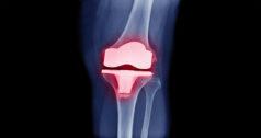
Sensors can be integrated into the tibial component of knee prostheses to measure force. Intra-operatively, forces in the medial compartment can be compared to the lateral compartment to achieve ligament balance. Post-operatively, forces can be measured during dynamic activities to predict wear rates and provide feedback to patients on “safe” activities. Likewise, force sensors incorporated into total disc replacement can guide patients on proper techniques to reduce loads on the spine.
The technology has other applications in orthopaedic surgery, including measurement of local temperature around implants as an indicator of infection or micro motion as an indicator of aseptic loosening. Many other applications for this technology in daily orthopaedic clinical practice will take advantage of quantitative monitoring of implants after surgery.
Dr. Ledet joined the faculty of the Department of Biomedical Engineering at Rensselaer in 2004 after having spent eight years as Director of the Orthopaedic Research Program at the Albany Medical College. Ongoing collaborations with the Division of Orthopaedic Surgery and Division of Neurosurgery at the Albany Medical College, and the Department of Orthopaedic Surgery at the University of Rochester School of Medicine and Dentistry have facilitated rapid translation of his research into clinical practice.
Dr. Ledet’s research has been funded primarily through industry sponsored grants and foundation grants, including prestigious awards from the Musculoskeletal Transplant Foundation and North American Spine Society. He is an active member of the Orthopaedic Research Society, the Biomedical Engineering Society and the North American Spine Society.


