


 Copy to clipboard
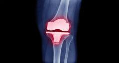
Orthopedic surgery consists of operations performed to address problems that develop in the bones, joints and ligaments of the human body. Such operations include the implanting of artificial hips, knees, spinal implants, plates and screws to treat broken bones, and joint fusions and implants to treat arthritic conditions. Physical conditions such as a broken bone, could require surgery to correct the problem and, thus, drilling of the bone. It is often necessary for bones to be drilled, cut or shaped by the surgeon to secure the implant to the bone (Figure 1) in order to allow healing to occur and the patient to resume normal activity.
The Challenge Facing Surgeons
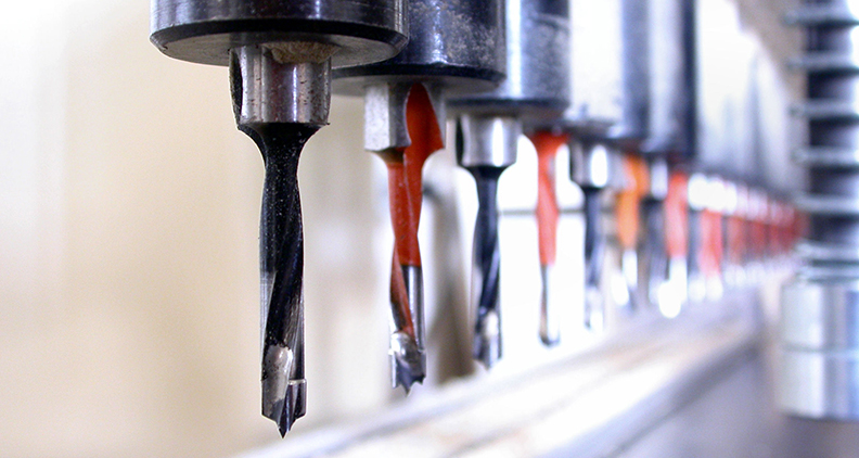
When drilling bone, orthopedic surgeons are faced with several challenges. Simply put, the progression of drill wear is not self-evident to a surgeon, locking them into making judgment calls on drill replenishment based on feel of drilling. Bone drills (Figure 2) are often reused without the benefit of tool wear data. This results in the use of drills that have become dull or are discarded when they still have useful life. According to the Association for Surgical Technologists, the reuse of single-use devices is encouraged by healthcare facilities in order to provide efficient, cost-saving medical/surgical care. [1]
Dull and inefficient bone drills, combined with poor geometries and poor chip evacuation, increase heat transfer from drilling into the bone. This heat generation can be beyond the ability of the bone to recover, which can ultimately result in bone death. “While the exact temperature at which thermal osteonecrosis occurs has not yet been determined, 50°C is the accepted critical value, as bone regeneration is almost completely impaired from this point on.” [2] In addition, bone drills that perform poorly create surgeon frustration and unnecessarily lengthen surgeries. Unfortunately, complications arising from localized bone death due to heat from bone drilling have not been well studied. There are studies of screw fixation, in which screws back out of the bone following surgery. A potential contributing cause to fixation failure may be that the screws are fixed to bone that has suffered heat damage from drilling temperatures beyond the bone’s ability to regenerate.

Figure 1: Orthopedic Plate and Screws
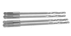
Figure 2: Orthopedic Drills
Research Begins for a More Efficient Drill
Work was undertaken at The Oregon Manufacturing Innovation Center, Research & Development (OMIC R&D) to study these issues. OMIC R&D is a world-class collaborative environment bringing together industry, higher education and government to develop new tools, techniques and technologies to address near-term manufacturing challenges through applied research. Stemming from many years of cumulative aerospace and industrial manufacturing experience, the OMIC R&D researchers were aware of drilling state-of-the-art solutions offered by manufacturers such Walter, Seco, Kennametal, Sandvik, Mitsubishi, OSG, IMCO and Sumitomo. These manufacturers invest thousands of dollars into their product developments, and tools are subjected to severe internal testing before release into the market. It became alarmingly apparent to OMIC R&D researchers as to how outdated the geometries on orthopedic drills are, and how little testing was conducted for tools used in orthopedic operations. [3] OMIC R&D researchers, along with undergraduate researchers from Oregon Tech, went to work with the goal of developing a bone cutting drill that is more efficient with a longer, more predictable cutting life, while generating less heat transfer to the bone than drills currently used in orthopedic surgery.
Drill Selection
3.5mm orthopedic screws are likely the most common screw size used to fix bone fractures in the body. These are used in the tibia, fibula, radius, ulna, humerus, pelvis, clavicle and foot bones. To install these 3.5mm sized orthopedic screws in bone, 2.5mm surgical drills are commonly used to pre-drill the opening. This test utilized drills from two of the top 10 global orthopedic device companies, denoted as Drill (company) A & Drill (company) B in this article. [4] Orthopedic surgeons would be familiar with the drills that were selected and the companies that produce them. This would provide a familiarity that is beneficial to the long-term aims of this study, which are to design a better bone cutting drill that can be adopted quickly and with confidence to the field.
OMIC R&D’s cutting tool members also participated in the testing, denoted as Drill (company) C & Drill (company) D in this article. Company C provided a stock drill that was intended to cut aluminum. Company D provided a prototype drill intended to cut bone-like material.
Test Material Selection
Bone is composed of two different densities: a harder, dense outer layer (cortical) and a soft, spongy inner layer (cancellous) (Figure 3). A worst-case scenario (most dense) bone was selected that would see use of this drill, which is the weight bearing tibia bone. Literature review was conducted to determine density of the tibia. Our research showed 69.98 lb/ft3 to be the density of the cortical layer at a midshaft location and 20 lb/ft3 to be the density of the cancellous layer. [5] [6]

Figure 3: Cutaway views of bone
Bone substitutes for orthopedic testing are commonly used for biomedical related evaluations. They have the same characteristics between manufactured batches and are used by orthopedic companies globally. Sawbones is a company located in Washington state that makes such products. OMIC R&D determined two comparable types of bone substitutes for human cortical bone. These types are expanded polyurethane of 50 lb/ft3 (Figure 4) and glass filled epoxy of 82 lb/ft3 (Figure 5).
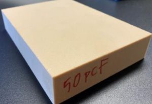 Figure 4: Cortical layered test material |  Figure 5: Bone from test material |
Machines, Testing and Measurement Methods
The Okuma M560 mill (Figure 6) was selected to conduct this test. Holes were drilled while clamped in a standard Kurt vise using a collet chuck (Figure 7). To simulate a bone drilling operation where the drill is used intermittently, and have consistent data, one input of the testing was to allow drills to return to ambient temperature. The drill was programmed to revolve in air for 10 seconds between holes. This dwell time was determined by the operator from touching the drill with bare hands after 10 seconds and determining it to not be warm to the touch.
 Figure 6: Okuma M560 3-Axis Mill |  Figure 7: Drilling Bone foam |
The Shimpo FG-7000L-S-1 force gauge (Figure 8) used to determine drilling force. The scale has a 1000 Hz sampling rate and provides graphs that were used to determine average drilling force over the 10mm drill depth. It was determined from literature references [2] and bench testing that 20.4 ± 2 lbs. would be the average amount of force a surgeon would apply to a hand drill for a drill tip of this size. It is important to recognize that OMIC R&D took necessary steps to replicate the forces as would be exerted by a surgeon during manually drilling bone. These nominal force values were then translated to cutting parameters (speeds and feeds) and programmed into the CNC machine (Okuma), thus creating a repeatable test condition that is relatable to those during surgery. This was verified by placing a scale on the milling surface, making minor adjustments until 20.4 lbs. was reached, then completing the rest of the testing at that drilling rate. An additional force measurement was taken during the final set of holes to ascertain if the drilling force of the final holes increased due to drill wear. The drill wear measurement equipment used was a Leica MC170 HD microscope (Figure 9).

Figure 8: Shimpo Force Gauge
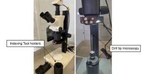
Figure 9: Drilling Bone foam
Summary of Testing Results
The test results allowed for understanding of the benefits and negatives of each drill.
Company A
| Company | A | Initial Feedrate | 35 in/min |
| Company Type | Medical/Orthopedic | Initial Force | 20 lbs. |
| Material | Bone foam 50 lbs./ft3 | Final Force | 25 lbs. |
| Holes Drilled | 510 | Wear | Minor Wear |
 Figure 10: Rake |  Figure 11: Face |  Figure 12: Hole 510 |
| Company | A | Initial Feedrate | 38 in/min |
| Company Type | Medical/Orthopedic | Initial Force | 20 lbs. |
| Material | Glass Filled Epoxy 82 lbs./ft3 | Final Force | 40 lbs. |
| Holes Drilled | 150 | Wear | Significant Wear |
 Figure 13: Rake |  Figure 14: Face | 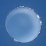 Figure 15: Hole 150 |
Benefits
- Having a Titanium Nitride (TiN) coating allowed for easier identification of wear.
Negatives
- Chisel tip is horizontal to the rake edge – it doesn’t allow material to flow directly into the rake, so chips are all mashed up together.
- Flutes are not prepped; they are straight edges – this causes wear because it focuses wear on a sharp edge leading to poor chip flow and tool heat problems.
- Surface is not polished; it is rough – leads to buildup problems.
- Gold coating is rough. You can see this on the pictures of the point. This exacerbates the material removal problems, heat and buildup
- Drill has buildup problems. Stainless steel material from the drill is pushed out toward edges of the drill – it is not clear why this happens. Possible causes could be because the drill is stainless steel; it deforms outwards toward edge, or could be because drill surface is not smooth. This buildup makes it hard for testing technician to remove foam or epoxy from the drill.
Company B
| Company | B | Initial Feedrate | 45 in/min |
| Company Type | Medical/Orthopedic | Initial Force | 20 lbs. |
| Material | Bone foam 50 lbs./ft3 | Final Force | 26 lbs. |
| Holes Drilled | 510 | Wear | Moderate Wear |
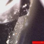 Figure 16: Rake |  Figure 17: Face |  Figure 18: Hole 510 |
| Company | B | Initial Feedrate | 33 in/min |
| Company Type | Medical/Orthopedic | Initial Force | 20 lbs. |
| Material | Glass Filled Epoxy 82 lbs./ft3 | Final Force | 92 lbs. |
| Holes Drilled | 150 | Wear | Significant Wear |
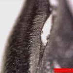 Figure 19: Rake | 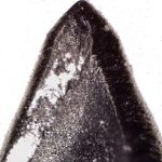 Figure 20: Face | 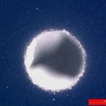 Figure 21: Hole 150 |
Benefits
- Relatively smooth surface finish provides less friction when removing material, therefore less wear on the drill.
Negatives
- Flutes are not prepped, they are sharp – this focuses wear on the leading edge, causing poor chip flow and temperature problems.
Company C
| Company | C | Initial Feedrate | 37 in/min |
| Company Type | Aerospace/General Mfg. | Initial Force | 20 lbs. |
| Material | Bone foam 50 lbs./ft3 | Final Force | 20 lbs. |
| Holes Drilled | 510 | Wear | None |
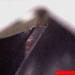 Figure 22: Rake |  Figure 23: Face | 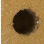 Figure 24: Hole 510 |
| Company | C | Initial Feedrate | 35 in/min |
| Company Type | Aerospace/General Mfg. | Initial Force | 20 lbs. |
| Material | Glass Filled Epoxy 82 lbs./ft3 | Final Force | 20 lbs. |
| Holes Drilled | 150 | Wear | None |
 Figure 25: Rake |  Figure 26: Face |  Figure 27: Hole 150 |
Benefits
- The tool has polished surfaces and almost no machining lines, which help carry material away better.
- Edge prep on rake is 0.001” and 0.0005” on flutes, this reduces wear typically seen in drills with sharp edges.
- Chisel tip is oriented to drive material into the rake. It gives the material an immediate place to go. Therefore, the chips are nicely formed and symmetric.
- Material is carbide so it shows considerably less wear compared to stainless steel drills.
Negatives
- The drill point angle isn’t small enough to allow for off axis drilling as would occur in surgery.
Company D
| Company | D | Initial Feedrate | 46 in/min |
| Company Type | Aerospace/General Mfg. | Initial Force | 20 lbs. |
| Material | Bone foam 50 lbs./ft3 | Final Force | 20 lbs. |
| Holes Drilled | 510 | Wear | Minor wear at 350 holes |
 Figure 28: Rake | 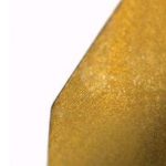 Figure 29: Face | 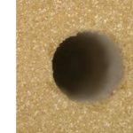 Figure 30: Hole 510 |
| Company | D | Initial Feedrate | 55 in/min |
| Company Type | Aerospace/General Mfg. | Initial Force | 20 lbs. |
| Material | Glass Filled Epoxy 82 lbs./ft3 | Final Force | 20 lbs. |
| Holes Drilled | 150 | Wear | None |
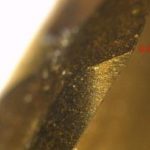 Figure 31: Rake |  Figure 32: Face | 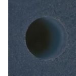 Figure 33: Hole 150 |
Benefits
- Drill point angle was small enough to allow for off axis drilling
- The chisel point is small, reducing the portion of the drill that is forced into material, causing the drill to wear more slowly.
- Had a faster drill advancement than all other drills (46 in/min in foam and 55 in/min in epoxy). The faster feed translates to less force if ran at feeds similar to other tested drills.
- Material is carbide so it shows considerably less wear compared to stainless steel drills.
Negatives
- Wear pattern in bone foam – long term the drill starts to wear. No wear in the epoxy.
- The drill had little to no Edge Prep, this caused a minor difference in wear for bone foam as compared to Drill C.
Recommendations to Industry
The following are recommendations to drill manufactures looking to create or improve an orthopedic drill.
- Drill life improved considerably for drills using an edge prep of 0.001” or less on drill tip and flutes. Drills that had no edge prep suffered from excessive wear. The more abrasive the application, the greater the edge prep should be.
- Drills should have a small chisel point oriented to drive material into the rake; this reduces the area where you are brutally pushing through material. Chisel tips that are horizontal to the rake create terrible looking chips as they are being mashed together out of the flutes.
- Curved rake drills like ones used for aluminum machining allow for better material evacuation up the flute.
- Flutes to be made longer than longest hole so the full circumference of the drill shaft doesn’t rub the hole. Full circumference contact creates heat and when drilling foam; it prevents the drill from drilling deeper than the flute length.
- A smooth surface polish on drill flutes and drill tip will allow material to be more freely evacuated. Grind marks on the flutes of current market drills likely hamper material evacuation and result in increased wear.
- Alternatives to stainless steel would yield drills that were considerably more wear resistant. Medical grade cobalt chrome is commonly used in implants in orthopedics and would be readily accepted into use if its performance was superior to Stainless Steel 455. Alternatively, research completed has shown carbide to be used in certain orthopedic drills but is not widely accepted into use. It is undetermined if the cause of this is cost or issues with drill fragility due to increased hardness over toughness. OMIC has concluded that there are some alloys of carbide that would sustain the use conditions of hospital operating rooms and be acceptable to FDA. Resources should be devoted to testing and FDA approval of carbide orthopedic drills because of demonstrated longevity and superior ability to cut bone over stainless steel 455 drills.
- Three drill flutes in are unnecessary. Because of the very low wear shown with two flutes, additional drill flutes will not dramatically improve performance.
References
[1] Association of Surgical Technologists, “AST Guidelines for Best Practices in the Reuse of Single-Use Devices in Surgery,” 9 April 2018. [Online]. Available: https://www.ast.org/uploadedFiles/Main_Site/Content/About_Us/Guideline_Single-Use_Devices.pdf. [Accessed 11 January 2021].
[2] K. N. Bachus, M. T. Rondina and D. T. Hutchinson, “The effects of drilling force on cortical temperatures and their duration: an in vitro study,” Medical Engineering & Physics, Salt Lake City, 2000.
[3] R. K. Pandey and S. S. Panda, “Drilling of bone: A comprehensive review,” US National Library of Medicine, 2013.
[4] Orthopedic Design and Technology, “The 2019 Top 10 Global Orthopedic Device Firms,” 14 August 2019. [Online]. Available: https://www.odtmag.com/issues/2019-08-14/view_features/the-2019-top-10-global-orthopedic-device-firms-955005/. [Accessed 11 January 2021].
[5] R. F. Capozza, J. Rittweger, P. S. Reina, P. Mortarino, L. M. Nocciolino, S. Feldman, J. L. Ferretti and G. R. Cointry, “pQCT-assessed relationships between diaphyseal design and cortical bone mass and density in the tibiae of healthy sedentary and trained men and women,” Hylonome, 2013.
[6] Food and Drug Administration, “Bone Anchors – Premarket Notification (510(k)) Submissions,” 2020.
[7] C. Timon and C. Keady, “Thermal Osteonecrosis Caused by Bone Drilling in Orthopedic Surgery: A Literature Review,” US National Library of Medicine, 2019.
OMIC R&D is a world-class collaborative environment bringing together industry, higher education and government in partnership to develop new tools, techniques and technologies to address near-term manufacturing challenges through applied research and advanced technical training. OMIC R&D is modeled after the University of Sheffield Advanced Manufacturing Research Center (AMRC) in partnership with Boeing in Sheffield, England. The OMIC R&D collaborative partnership is located in Scappoose, Oregon in a facility owned and administered by the Oregon Institute of Technology (Oregon Tech).
Authors
Joshua Koch, Business Development Officer, OMIC R&D
Josh Federspiel, former, Biomedical Solutions Researcher, OMIC R&D
Cody Apple, Machining Solutions Researcher, OMIC R&D
Trent LaMont, Mechanical Engineering student, Oregon Tech