


 Copy to clipboard
Design for Manufacturability (DFM) has been used for decades for good reasons. In the early 1980s, Dr. Geoffrey Boothroyd and Dr. Peter Dewhurst developed analytical techniques focusing on design for manufacturability and assembly (DFMA). The purpose of applying DFMA is to identify, quantify and eliminate waste or inefficiency in product design.1 During this period, U.S. manufacturing quality was playing catch-up. It was common for new designs to be “tossed over the wall” to manufacturing. Often quality issues were then found in the early stages of production and plagued product quality for the life of the product. Early DFM gave manufacturing a voice in the design process. Today, DFM is still viewed as an opportunity to provide manufacturing input during the design process, with the real benefits of DFM extending well beyond approval from manufacturing.
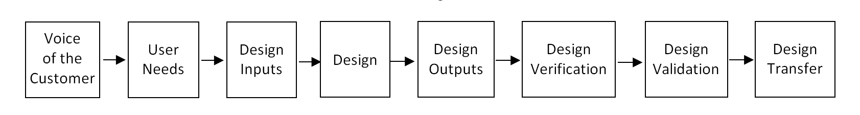
A successful product meets a market need, at a price the market is willing to pay, at a time when the market wants it. DFM can influence all three areas. To understand how DFM can be leveraged to contribute to a product’s success, we need to understand the design process. The design process contains eight main components (See Exhibit 1.), starting with gathering voice of the customer (VOC). The next step is translating VOC into user needs. The design is then refined by determining design inputs. Once defined, design inputs are translated into actual product designs in the form of drawings, models and specifications. All design outputs should tie back to a design input, which in turn should relate to a user need. Every feature on an engineering drawing should be able to be traced back to a user need. For example, a material callout on the drawing of an implant of “Titanium 6-4 per ASTM F136” would be traceable to a user need of “must be biocompatible.” Similarly, a rounded edge radius could be traced back to a user need of “no adjacent tissue damage during insertion.”
Exhibit 1: Design Process
|
Design verification is checking that design outputs meet design inputs. Design verification confirms that the design meets the user needs—was the correct product designed. There is often confusion concerning the difference between design verification and design validation. Design verification according to 21CFR 820.30 is “confirmation by examination and provision of objective evidence that output meets input requirements,” whereas design validation is “the establishment by objective evidence that specifications (specified requirements) conform with user needs and intended use(s).”2 Design verification answers the question, “Did I make the design correctly?”, whereas design validation answers the question, “Did I make the correct design?”3 The final step of design transfer is the process of conveying design output into production specifications. Design transfer often includes requirements for special process validations, assembly method qualifications, inspection methods, etc. The conclusion of design transfer typically contains a design transfer confirmation document wherein evidence is provided that the necessary design transfer elements have been completed.
DF(x) Design For…
Many subcategories fall under the broad definition of DFM. As noted earlier, there is design for assembly, which can be further refined as design for manual assembly and design for automated assembly. There is design for inspection. There is design for low product cost, which spans from cost/optimization of raw material to manufacturing direct labor to packaging/transportation cost. There is also design for low project cost, which refers to design output options that have various impacts on project costs and project timelines. Other costs not usually considered in traditional approaches to DFM include inventory cost, non-recurring engineering cost, machine set-up cost, special process validation, capability runs, manufacturing efficiency and total throughput.
Start Early in the Design Process to Optimize Opportunity
As noted, many areas of potential benefit exist throughout the design process. The first key to leveraging DFM is that the activity must start early. Most of the potential benefits will be lost if waiting until design transfer when the product’s design and design verification/validation testing have been completed. DFM activities should begin when evaluating design inputs. For example, a user need of “must slide freely” on an instrument shaft may be translated by the product development engineer to a design input of “low friction coating,” anticipating a design output of “titanium nitride coating.” In this example, let’s assume that titanium nitride coating has not been validated on stainless steel, but low friction chrome coating has been validated. If the chrome coating meets other user needs, the product engineer’s decision to use titanium nitride will add significant cost to the project and will likely affect the project timeline and product cost.
Product development leadership can leverage DFM through these other considerations.
Design Considerations
Exhibit 2: Parametric Model
|

Time to market is also critical in the orthopedic device industry. Product engineers can shorten design time using parametric design modeling when a product has essentially the same features across a range of sizes. In a parametric design, the engineer creates relationships that cause design elements to self-adjust to certain design variables, such as length or diameter. Early in the design process, an engineer may choose to develop a range of sizes from one parametric model and a tabular drawing rather than one model and drawing for each size. As the design evolves, the engineer needs only to make changes to one model for the entire range of sizes. A two-dimensional drawing would then list dimensions for design variables and parametric elements in a table. In some situations, a parametric approach can result in havoc-inducing product and project costs and increasing project timelines.
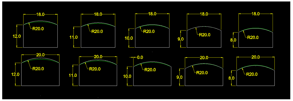
Let’s look at a simple example. The parametric variables for a basic shape are width (W) and height (H) with a top profile radius defined by a center that is located vertically below the part at H and horizontally at W/2. (See Exhibit 2.) For this product there are five heights, from 8.0 mm to 12.0 mm in one-millimeter increments. There are two widths, 18mm and 20 mm. The radius of the top profile is defined by the combinations of width and height.
The result would be ten different designs based on the five heights and two widths. The parametric derivation of the top profile radius results in ten different radius dimensions. Exhibit 3 shows the resulting designs and the unique top profile radius for each. While it would be quite easy for a design engineer to create such a parametric model and two-dimensional drawing, the impact on manufacturing and inspection is significant.
Exhibit 3: Parametric Design Iterations
|

Assuming the top profile is manufactured by milling, essentially there would be two options—profile milling, which is very time consuming, or use of ten different special profile cutters. Either option results in increased cost for machining, setup, tool management, etc. In addition, inspection of the top profile would typically be done using a comparator/overlay or, depending on datum structure and other detail that may be included in the top, by a coordinate measuring machine. Again, in either case, what could have been inspected with one method will now require ten.
Would a fixed radius design be possible? Exhibit 4 shows a fixed 20mm radius top profile applied to the entire range of sizes. The maximum difference between the parametric derived radius and the fixed radius is 0.7 mm. Is this acceptable? Again, we look at user needs and design inputs. Is there a user need that requires a top profile radius to be parametric to the height and width?
Exhibit 4: Non-Parametric Design Iterations
|
This example is an over-simplification of the risks of parametric designs. Actual designs are more complex and usually have a larger range of sizes that include more than width, height and depth, further complicating the design.
Material Considerations
Product development engineers are often drawn to new technology. When the new technology involves use of a new material, there are risks. Some issues with new materials, such as biocompatibility, are identified early and necessary actions are taken. There is, however, a more dynamic issue when a device requires a new material related to availability when the product is eventually put into production. Limited production at the supplier and demand from other users can result in unacceptable lead times, causing launch delays. The specification of a new material should be verified by tracing back to a user need. Failure to trace back to a specific user need that can only be satisfied by the new material should raise questions about using the new material. After deciding that a new material is justified, it’s critical to involve appropriate resources from procurement and production planning early in the process.
Product Launch Considerations
The DFM team should also be aware of the initial size of the product launch. For smaller launch quantities, special consideration should be given to indirect product cost. Non-recurring engineering for development of the manufacturing process and inspection methods can be significant for small quantities. Fixtures or molds can also add significant cost and time to the project for qualification/validation. A design that creates a new worst case for a special process will require re-validation of that process, which can be very expensive and time consuming. For lower launch quantities, the team should consider design alternatives that avoid these costs.
Throughput Considerations
Another area of opportunity for DFM is manufacturing throughput time. Throughput time is different from lead-time. Lead-time is the time from when an order is placed until the moment that order ships. Lead-time includes ordebacklog time. Throughput-time is the time from the start of production until the product is complete. A design that has requirements for special processes that are proprietary or have limited sources will result in logistical challenges. The parts need to be packaged and shipped to the supplier for processing and wait in queue for processing. After processing, the parts must be repackaged and shipped back. Upon return, the parts are queued for incoming inspection. This can easily take two to three weeks, if not more. Having multiple special outsourced processes can add months to throughput time. A requirement for a special or proprietary outsourced process should be verified by tracing the design output back to a clear user need.
Datum Structure Considerations
An often-missed opportunity in DFM is analysis of datum structure for geometric dimensioning and tolerancing or GD&T. The datum structure should be determined first by the function of the device. However, if the datum structure is not critical to the function of the product, the datum structure is often developed to make inspection easier. The datum structure can determine the manufacturing processing and fixturing needs. For example, a datum structure can prevent balancing work on the main and sub spindles of a swiss lathe. The design team should consult subject matter experts in manufacturing and inspection when developing datum structure for a new product.
Material Removal Considerations
A general guideline in DFM in a machining environment is to remove as little material as possible. Consideration for available raw material size can impact not only the utilization of the material, but also reduce machining time.
Exhibit 5: Handle Shaft
|
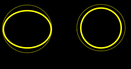
Consideration should also be given for efficient methods of material removal. Exhibit 5 shows two options for a handle shaft, one round and one an oval shape. The dotted circle represents the raw material from which the handle will be machined. In both options the amount of material removed is essentially the same. However, the round shape can be turned efficiently and will be a lower cost than the oval shape. Tracing the design output back did not find a user need requiring the shape of the handle to be oval. However, marketing stated that there is a need to differentiate from existing products, and the handle needs to have a more modern appearance.
DF(x) Considerations
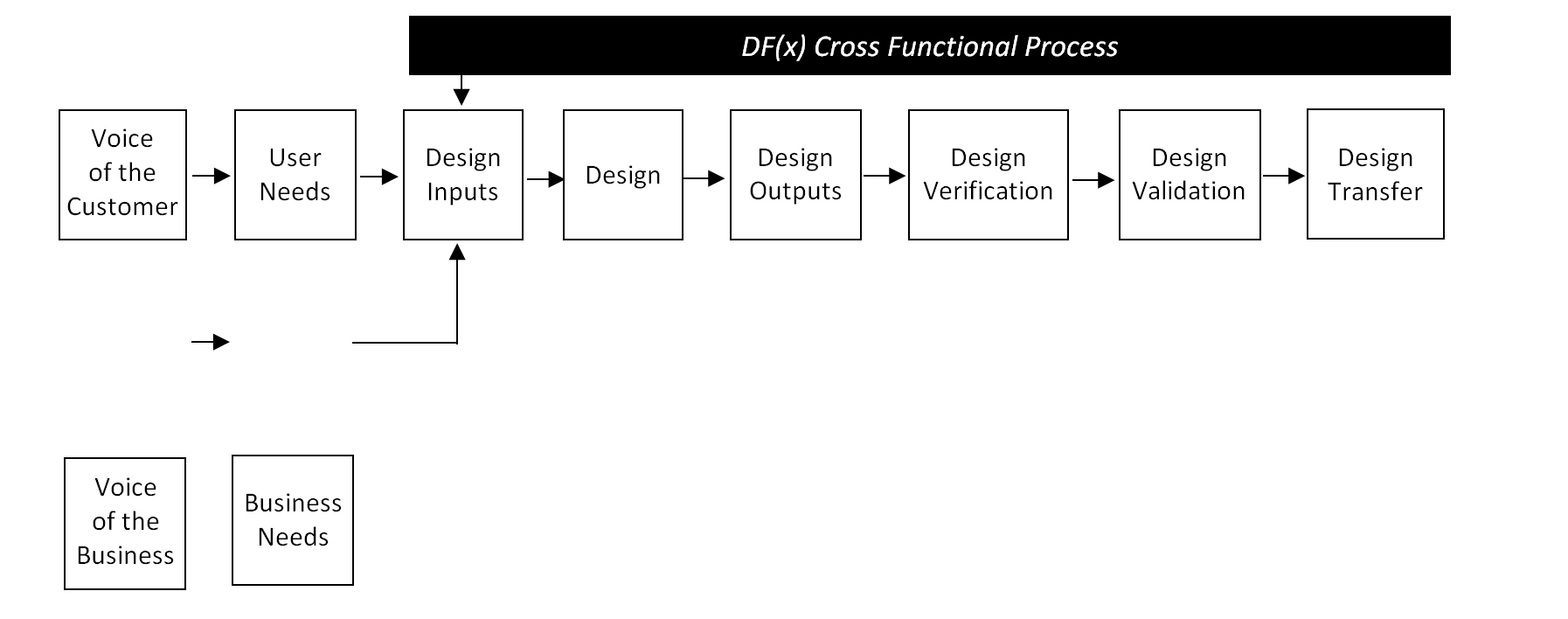
Herein lies the need for an updated approach to the traditional design process. In the traditional design process, design inputs are derived from user needs, which are translated from VOC. However, as just noted, there are design inputs that originate not from the user’s needs, but from other sources such as marketing. These other needs can be driven from internal business needs such as cost targets needed to make the project viable to external needs, such as regulatory requirements. An updated approach to the design process for DF(x) shows a pathway to define design inputs based on business needs. (See Exhibit 6.) This approach allows for clear traceability of design outputs back to customer or user needs. DF(x) team members can then validate design inputs and outputs when considering alternatives. Priorities must be clearly stated for business needs. Should a project be delayed in order to achieve cost targets? Should marketing requests carry the same importance as customer needs?
Exhibit 6: DF(x) Design Process
|
DFM Conflict of Interest?
Is there a potential for conflict of interest in DFM practice? Would a supplier possibly be motivated to manufacture a costly design? A costly design would increase the revenue for the supplier, and would likely increase profits, too. The supplier may have excess milling capacity—why steer a customer away from profile milling to a lower cost alternative? Maybe in the past, a supplier’s request for design changes was rejected. In an environment where customers are expecting price reductions year after year, would a supplier want to provide DFM input that would result in an efficient, low-cost version with little opportunity for future cost reductions? The same is true for internal manufacturing facilities, which are also under pressure to meet annual cost reduction objectives. The article, “The Orthopedic Business Model” in the March 2019 issue of BONEZONE indicates that, in most situations, manufacturing demand plummets after the initial launch. Finding cost reductions with declining volume is certainly a challenge, especially if the design and manufacturing process were optimized using DF(x). It’s an interesting question.
Summary
What are the keys to unlocking the benefits of DFM?
- Change the approach from DFM to DF(x). Focus on not only designing for manufacturability, but design for inspection, assembly, low cost, manufacturing efficiency, business needs, manufacturing throughput, packaging/transportation, etc.
- Start early. DF(x) activities must begin when design inputs are being developed and translated into designs.
Include cross-functional expertise. - Define the priority of customer and business needs.
- Trace outputs back to needs. Use this test to evaluate design alternatives to avoid costly and time-consuming options.
- Be careful of parametric designs. A product development engineer might be aware that the time saved up front could be lost downstream.
- Be mindful of the potential for conflicts of interest. If suspicions arise, consider independent review.
DF(x) is an updated approach to traditional DFM. It addresses a wider range of benefits and provides a structured approach to new product development.
References
1. Boothroyd, G., Dewhurst, P. and Knight, W., “Product Design for Manufacture and Assembly, 2nd Edition.” Marcel Dekker, New York, 2002.
2. Code of Federal Regulations, Title 21, Volume 8, Part 820 – Quality System Regulation, Subpart C-Design Controls, 2018.
3. Liu, S., “Design Controls, FDA Small Business Regulatory Education for Industry,” 2015.
Dale Tempco is a consultant specializing in product development, operations, quality, supply chain, M&A and finance with expertise in low-cost sourcing, design transfer, DFM, special process validation, cleaning validation, additive manufacturing, failure analysis, cost accounting and extensive experience in China.