


 Copy to clipboard
The orthopaedic industry has received heightened publicity for all the wrong reasons, with particular emphasis on failures in hip joints. Since the introduction of modular heads for total hip replacement (THR) surgery in the 1990s, concerns have been raised over the potential for fretting and corrosion of these devices. Some case reports showing corrosion in small diameter heads are available in the literature. These issues were related to material combination or lack of taper lock.
Recently, the taper junction has come into the spotlight as a major source of hip joint failure, with the American Society for Testing and Materials (ASTM) taking the step of producing a soon-to-be-released “Standard Guide for the Characterization of Material Loss from Conical Taper Junctions in Total Joint Prosthesis.” The guide covers measurement of depth of material loss and volume of material loss and taper geometry using a roundness machine and coordinate measuring machine (CMM).
Taper Measurement in Manufacturing
Tapers on implants are stringently controlled during the manufacturing process. The critical-to-quality (CTQ) parameters are angle, diameter at depth, roundness, roughness and straightness, with typical tolerances given in Exhibit 1.
Exhibit 1: Typical tolerances for taper junctions
| CTQ Parameter | Typical Tolerances |
| Angle | +/- 0°2’…+/- 0°3’ (+/- 0.033°…+/-0.05°) |
| Diameter at Depth | +/- 0.001 in (+/-25 µm) |
| Roundness | +/- 0.0002 in … +/- 0.0004 in (+/- 5 µm … +/- 10 µm) |
| Roughness | 16 µin … 63 µin (0.4 µm … 1.6 µm) |
| Straightness | +/- 0.0001 in … +/- 0.0002 in (+/- 2.5 µm … +/- 5 µm) |
Historically, manufacturers required inspection equipment to demonstrate Repeatability and Reproducibility of 20 percent, but there is an industrywide shift to reduce this to ten percent, placing ever more stringent requirements on the manufacturers of inspection tools. Measuring taper angles with a repeatability of around a thousandth of a degree quickly and independent of an operator is not an easy task and many conventional, mechanical inspection systems or air gauges struggle to achieve this performance.
With optical CMMs, the required repeatability is easily achievable for all of the above CTQ parameters while reducing the cycle time. The images in Exhibit 2 show the data sets of a new head taper (left) and a stem taper (right).
Exhibit 2: New head taper (left) and stem taper (right)

Data courtesy of the national Centre for Advanced Tribology in Southampton (nCATS).
Once this point cloud has been acquired, the machine extracts the relevant CTQ parameters automatically, providing the user with a simple pass/fail assessment.
Taper Measurement in R&D
The requirements in an R&D environment are substantially different. Here, small changes in the taper surface during use in vitro or in vivo are of interest, namely the volume of material loss, depth of material loss and modifications in the surface texture.
A number of different inspection systems used to be required to answer these questions, and detailed measurements would often take hours or days to set up and measure. With an optical CMM, detailed measurements with nanometre resolution can be carried out within minutes, freeing up valuable time for data interpretation. Studies involving a large cohort of components can be completed within short time periods at the highest accuracy.
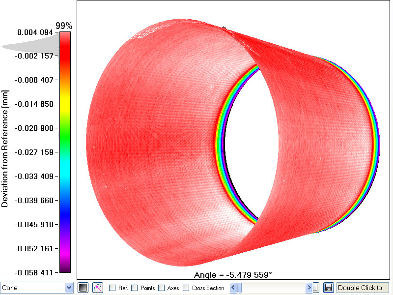
Exhibit 3 shows the data generated for a retrieved head taper (left) and a retrieved stem taper (right). The head taper, from a metal on polyethylene joint, has experienced significant material loss, while the stem taper shows changes in the surface texture. The thread that was originally machined into the surface of the stem taper has faded and grooves in the direction of the taper axis have appeared. These are thought to be the result of erosion.
Exhibit 3: Scan of a retrieved head taper (left) and stem taper (right) showing significant material loss and changes to the structure of the surface

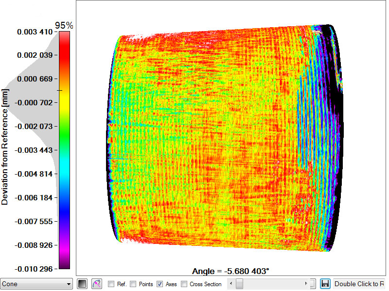
The color corresponds to the depth of material loss. Data courtesy of the national Centre for Advanced Tribology in Southampton (nCATS).
Conclusions
Optical CMMs have the capability to provide fast, detailed and highly accurate measurements of the taper geometry of modular hip prostheses without contact with the surface under investigation. There is no stylus or touch probe that could wear or damage the component. Having been used for the measurement of artificial joints in production and R&D for nearly ten years, they are now finding their way into standards and into many factories and laboratories.
Christian Maul, Ph.D., has been working in the field of non-contact ultraprecision metrology since 1997. In 2005, he founded RedLux Ltd, a company that specializes in the development of non-contact ultraprecision coordinate measuring machines for quality control in manufacturing and R&D, initially focusing on solving difficult measurement problems in orthopaedics. For several years he has been an active member of the ASTM committee F04 on Medical and Surgical Materials and Devices. Mr. Maul can be reached at +44-(0)23-8026-3095.
RedLux Ltd.
www.redlux.net