


 Copy to clipboard
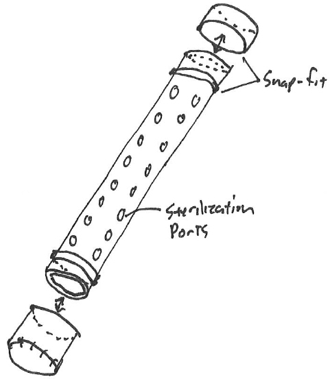
Napkin sketch
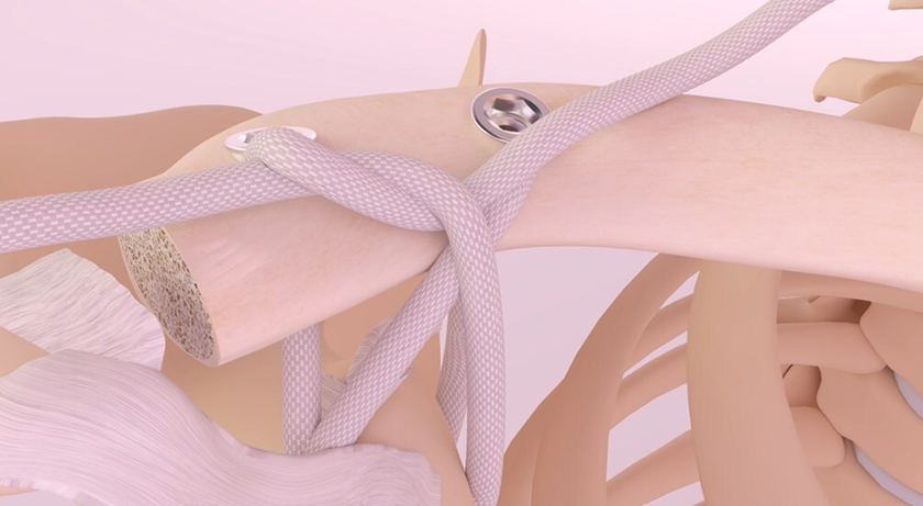
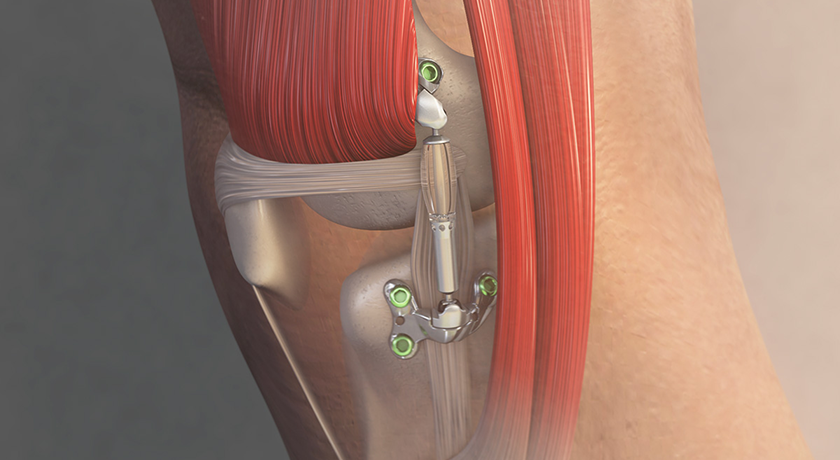
When developing medical devices that are subject to special controls per 21 CFR Part 820.30, Design Controls, we must be aware of paving the path to documented compliance. Let’s walk through a particular design problem received from the marketing team. The design problem is illustrated by the clinicians and/or marketing team as was shown in Exhibit 1.
The marketing team found that when a k-wire is retained in silicone brackets within a sterilization tray, the wires could become dislodged and potentially damaged during transport. The conversational solution entails, 1) contain the wires in a tube with sterilization ports that don’t allow extrusion, 2) hold the larger diameter tube more substantially in a bracket, and 3) consider that the lids can easily be removed and reattached.
Since a sterilization container is a Class II device per FDA Product Code KCT, or the container is device–specific, making it a Class II device, we’ll apply and document conformance to design control requirements.
820.30(a): General
The device is classified as Class II, requiring both GMP and Special Controls.
820.30(b): Design and Development Planning
Competent resources have been allocated to the project, and particular milestones have been set.
820.30(c) Design Inputs
The project reached the phase wherein FDA requires us to approve User Needs and Design Inputs. The Project Manager and Marketing Manager provided the details as shown in Exhibit 2 (focusing only on the snap-fit portion of the design inputs):
Exhibit 2: Design Traceability Matrix
| User Needs | Design Input | Design Output | Design Verification | Design Validation |
| Removable Lid Provides Access to K-Wires | Non-threaded Snap-fit: 6-15N Force | DWG: 10-Caddy Rev. A | Test Report #56 | Test Report #78 |
Design concept
Let’s begin our work.
The marketing manager did a good job of identifying a practical user’s need, and the project manager converted that into a measurable design input with range of attachment forces. This project has been identified as being time-sensitive (as usual), and we’re after that big promotion, so doing a round of prototypes will leave the management team dissatisfied.
To reduce the timeline, we’re committing to a production order on the first try without prototypes. We spend the morning designing in our CAD system, and present the team with the design shown in Exhibit 3.
Everybody seems to be happy with the general concept of the simple tube with caps. The last risk to the design (other than passing sterilization to SAL-6 and a dry time validation) is the attachment performance of the end caps. The tube is anodized 6061 aluminum, and the caps are made from medical grade Radel®. Exhibit 4 (on the next page) lends a closer look at particular elements of construction.
Here, Exhibit 4 shows that closer look at particular elements of construction.
Exhibit 4: Detail of Construction
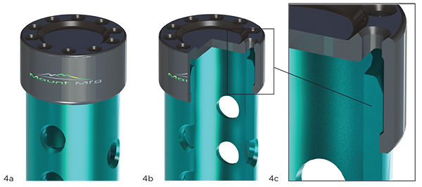
4a: Detail View, 4b: Partial Selection, 4c: Detail View
The interconnection of the cap to the tube is designed, but we’re unsure of the amount of attachment force that the proposed design requires to snap together. Since we’re unsure of this, we’ll run an analytical design of experiments, varying one of the critical dimensions: the interference between the tube and cap.
In this experiment, we’ll vary the interference by 0.30mm, 0.15mm and 0.05mm and check the resulting attachment force. The model was designed in Solidworks® and a finite element analysis (FEA) set up in Ansys® Workbench.
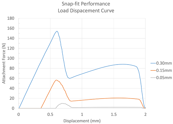
Exhibit 5: Load Displacement Curve
The resulting data from the simulation indicates performance of 5, 58 and 155 Newtons, depending upon the interference. This is depicted in Exhibit 5.
Nonlinear simulations with large displacements can involve thousands of time steps. This, combined with the typical engineering workstation, can mean ten to 20 hours of computational time. By simplifying the model down to an axi-symmetric study, the solution was found for each parameter in less than 30 minutes.
It’s likely a good guess that 0.30mm of interference, on what is essentially a press-fit, is going to result in an undesirable force. What’s great about these three data points is that we can make some assumptions on the interferences and performance that lie between our data points.
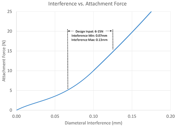
Exhibit 6: Interference vs. Attachment Force
If we take the peak forces and extrapolate the data between, we can find performance levels between the data points, as shown in Exhibit 6.If we had originally ordered a prototype design and performed bench testing on the device, we would have found that our attachment force is uncomfortably high, and that single data point would have cost the project eight weeks to manufacture the parts and perform test. Using simulation, we’re able to engineer the nominal force and also specify the appropriate tolerances that continuously result in a performance that meets the user’s needs.
Exhibit 5 takes the original data points and plots, and estimates the data points between each of the design configurations. Given the interference variations, the FEA indicates that a minimum of 0.07mm and a maximum of 0.13mm of interference can occur before it either slides on too easily, or is too difficult to slide together.
This data can be utilized in different ways when considering design inputs, outputs and design verification. With the current format of the design traceability matrix, the verification activity is performance-centric. The best method to document compliance would be to write a test protocol and establish or reference the design input requirements as acceptance criteria for the test, and then run this simulation and compare intended performance to predicted performance.
Alternatively, actual performance testing of physical specimens can be conducted. The problem with actual testing is that it will indicate performance in a single state of the design. Simulation provides insights not only on nominal performance, but the influence of tolerance on performance, making this method more comprehensive than a single physical test. Ideally, a single physical test would be conducted on the physical cap and tube to validate that the model is predicting appropriate values.
There are cons associated with Displacement (mm) relying on simulation data as the sole means for making a decision, if you’re inexperienced. It’s too easy to inadvertently apply improper boundary conditions, forces, contacts, mesh density or even material properties. It’s important to always check your error on receipt of the devices to get a historical under-standing of how accurate your simulations are.
Once you become proficient, those risks associated with error become surprisingly low. Most orthopaedic simulations are very simple mechanical problems that can be mastered without a significant time investment by the engineer. An entry level engineer can become proficient in fewer than six months, with frequent exposure to the software and a little guidance.
This concludes a single design problem and illustrates some of the major steps involved in designing devices in a regulated environment.
I’ve seen many different methods of design verification. The benefit of our design control regulation is that even if the design inputs were inappropriately specified, the subsequent design validation would have failed in meeting the user’s need, thereby preventing the design from hitting the market.
Using FEA allows us to more accurately predict whether or not our specifications will result in a design that’s satisfactory, sometimes in more detail than physical testing of actual prototypes.
Eric Lintula is an industry professional with management experience in design, regulatory affairs and quality systems. He is the founder of Mount Mfg., LLC, an early-stage company that supports OEMs with rapid prototyping, production equivalent prototyping and consulting services. Lintula has also served in engineering leadership positions for Nexxt Spine, Paragon 28 and Pioneer Surgical. Mr. Lintula can be reached by email.